To MENU
Printed circut board "hand drawn" :)
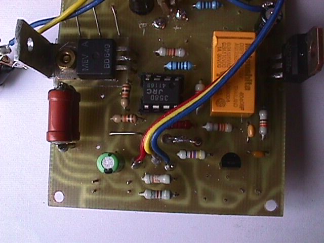
Charger part view
Discharger part view
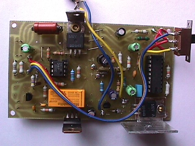
View of all circuit
Case top view
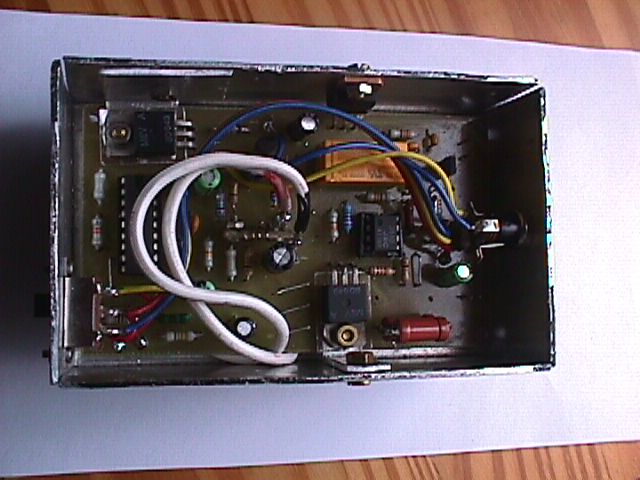
View inside the case from bottom
70cm UHF Mini Yagi antenna
To Main MENU
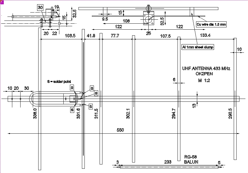
Below there is one description of my mini yagi UHF 430-440 MHz Yagi antenna. The center
frequency is 434 MHz. The antenna is used for packet radio on that band and has
the gain of about 13 dB. The antenna is pretty directional (horizontal angle +/- 10 degrees) and
with good polarization surpression. If you will built it, please make exact dimmensions
as shown on the drawing. The decimals of mm can be omitted.
ANTENNA DRAWING
To MENU
 DRIVEN ELEMENT
To MENU
DRIVEN ELEMENT
To MENU
View of driven element with matching wires
SYMETRIZATION BALUN
To MENU
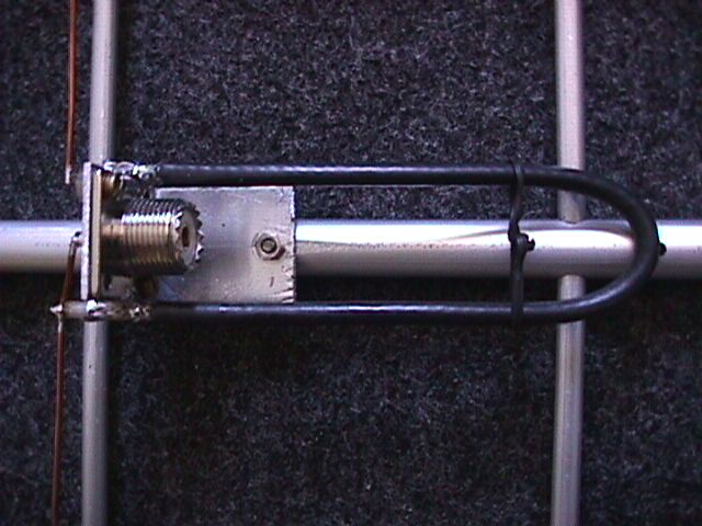
Symetrization balun from a piece of RG-58 full shield coax cable
FEED DETAIL 1
To MENU
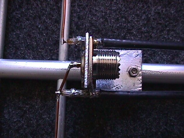
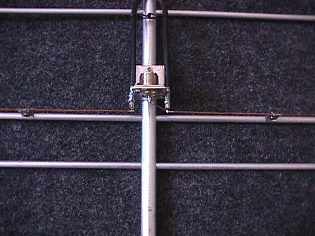
Driven element feeding assembly in detail 1
FEED DETAIL 2
To MENU
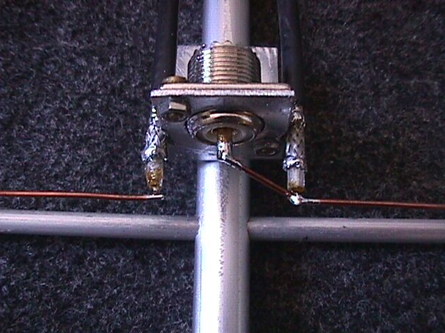
Driven element feeding assembly in detail 2
OVERALL VIEW
To MENU
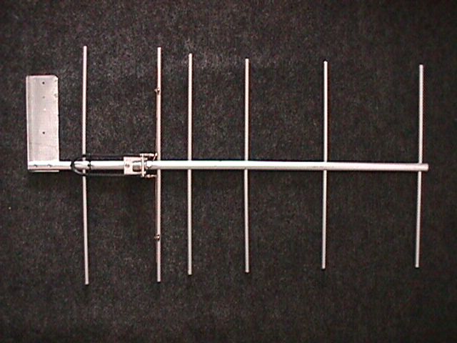
Overall view of the antenna. It's only 55 cm long.
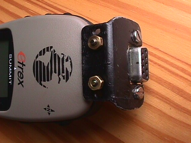
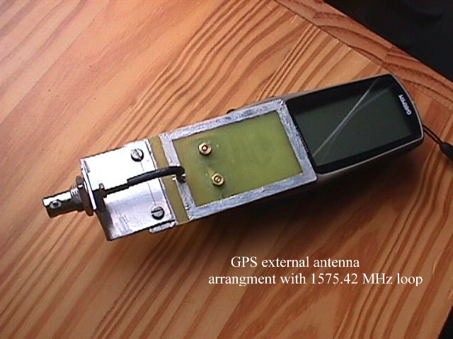
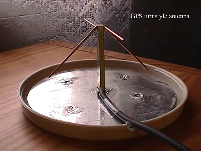
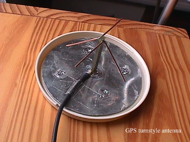
GPS external antena and coupling
to the GARMIN GPS receiver
To Main MENU
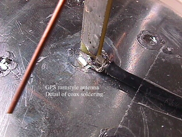
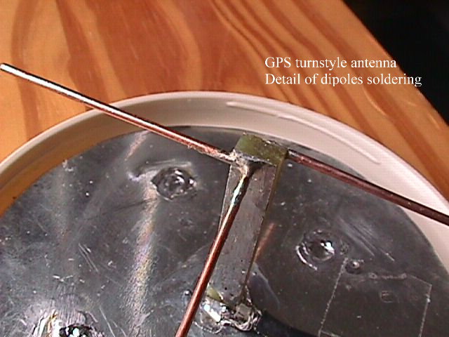
Below fotos of GPS turn-style miniantena and its coupling to GARMIN GPS receiver which
has no any connector for external antenna. Also shown DB-9 adaper to output GPS pins.
The pins are +3V RXD TXD and GROUND. Placing the antenna under the front window of the car
I receive minimum 7-9 satellites in one moment depending on surrounding country side.
Connector adapter - top view
To MENU
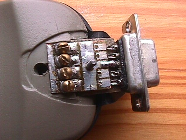
 Connector adapter - bottom view
To MENU
Connector adapter - bottom view
To MENU
Antenna coupler with BNC connetor
To MENU
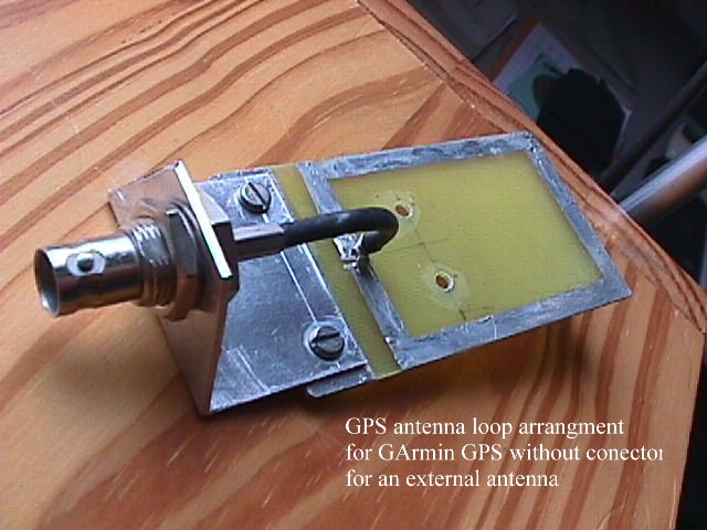
Antenna coupler mounted
To MENU
Driven element feeding assembly in detail 1
Antenna detail - coax connection
To MENU
Antenna detail - elements
To MENU
Antenna view from side
To MENU
Antenna overall view
To MENU
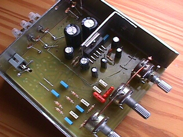
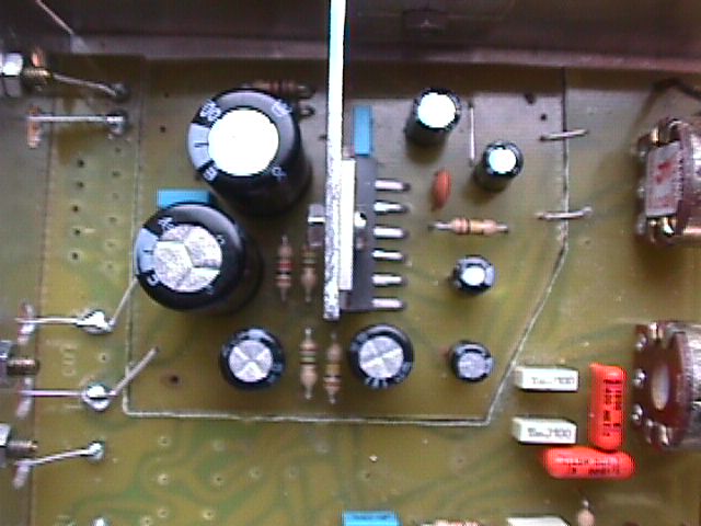
Audio amplifier with TDA2009A
To Main MENU
Below here is the description of my stereo audio amplifier using the chip TDA2009A.
This amplifier must have both speakers connected otherwise it is drawing high current
more then 1 A. Although the chip has the temperature protection inside it is not recommended
to switch the circuit without both speakers connected.
With the input signal the supply current at 12 Volts can reach upto 5 Ampers so good
12V/5 Amper power supply is needed. It can be supplied from the switched AT pc supply as well.
That's why also good radiator to be mounted to the amp case (not shown on photos).
SCHEMATIC DIAGRAM
To MENU
 View 1
To MENU
View 1
To MENU
View 1
To MENU
View 1
To MENU
CAR HERMETIC BATTERY CHARGER
To Main MENU
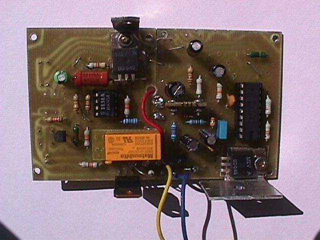
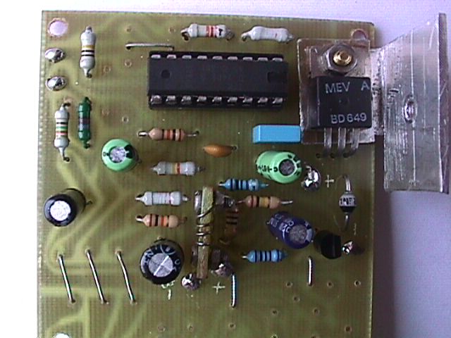
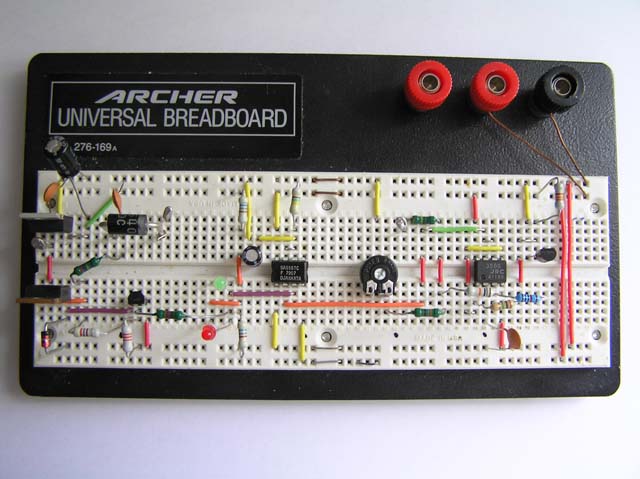
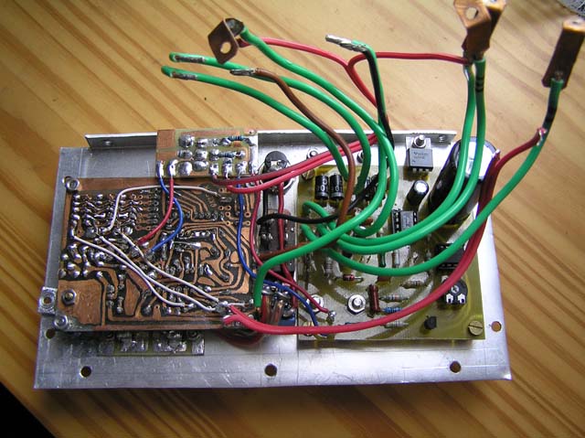
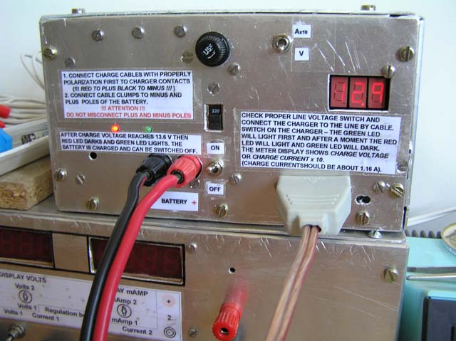
Below is the description and photos of the automatic car hermetic battery charger.
The charger is charging in mode of constant current of about 1 Amper. There is LM350
voltage regulator working as constant current supply. The charging process is fully
automatic. When the charge voltage reaches about 13.8 Volts the charging process is
changed into trickle mode and keeps the battery loaded with a periodical current impulses.
The charger is here built with the simple digital panel meter showing charge voltage
or current.
Schema of the charger
To MENU
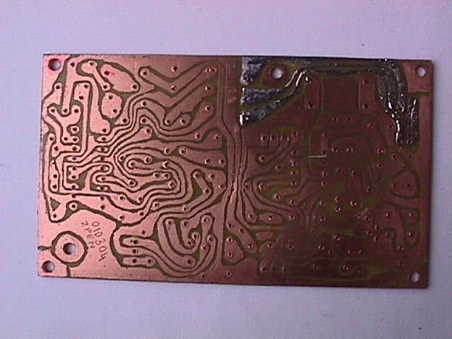
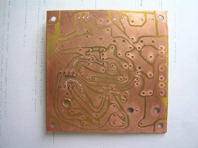
 PCB of charger
To MENU
PCB of charger
To MENU
Development
To MENU
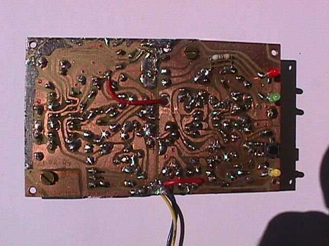
PCB bottom
To MENU
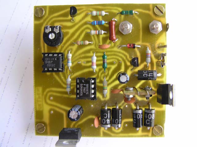
View from top
To MENU
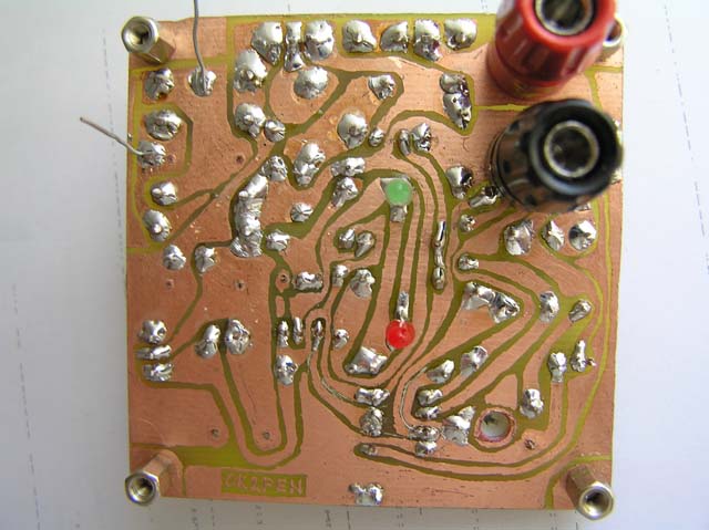
View from bottom
To MENU
Front panel mounting (rear side)
To MENU
Overall view
To MENU
Schema of panel meter
To MENU
PCB of panel meter
To MENU
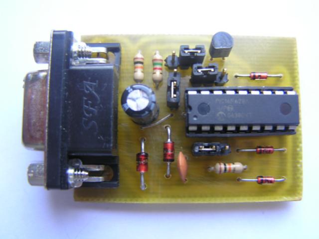
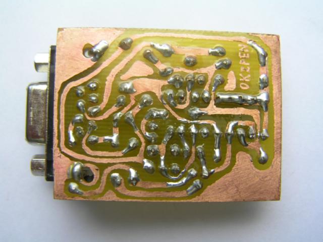
"JDM" Programmer for Microchip's PICs
To Main MENU
Below here is the description of a simple Microchip PIC "JDM" programmer. This programmer
cooperates with the soft in Windows. The programmer is connected to COM port of the pc.
Programmer can burn or erase most of types of the Microchip PICs.
The software "pp4u_082_en.zip" you can download in the section
Downloads. Case you will
have problems with the installation of the soft please see webpage
http://feng3.cool.ne.jp/en/rcd.html
The programmer works also with Linux soft "picprog-1.8.3.tar.gz" which you can also
download from section
Downloads but the author gives no function garantee.
The circuit board is 37x49 mm.
SCHEMATIC DIAGRAM
To MENU
 CIRCUIT BOARD
To MENU
CIRCUIT BOARD
To MENU
TOP VIEW
To MENU
BOTTOM VIEW
To MENU
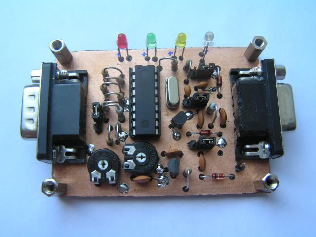
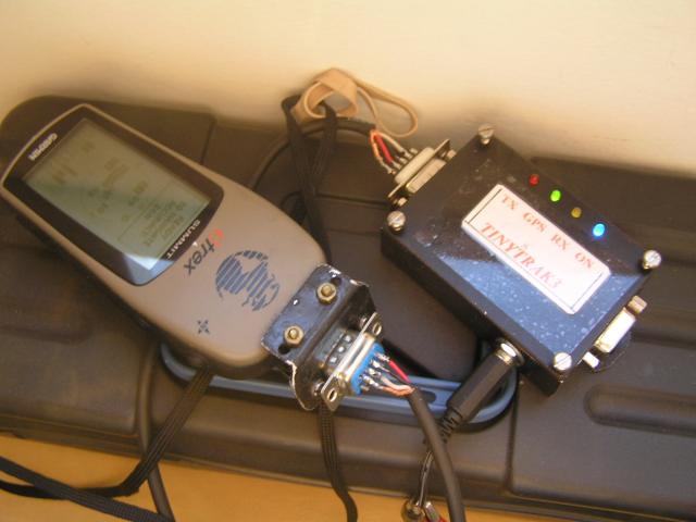
"TINYTRAK3 position tracker"
To Main MENU
Below is one of known constructions of the Tinytrak3 which is simple geografical
position tracker enabling transfer of GPS data to be transmited by amateur radio
into APRS net via APRS Digis. The Tinytrack is supplied by car voltage and switched
between the GPS and any type of ham radio. This construction can be made more small as this one
was made for test purposes. The radio on the Test picture is not connected.
The Tinytrak program for setting callsign etc. you can download in the section
Downloads as well as
the firmware for the PIC16F84-04/P.
During programming the PC is connected via Null modem to the GPS connector.
Tinytrack3 has here PIC16F84A-04/P with 10 MHz crystal and old Tinytrak (not
Tinytrak3) firmware. When Tinytrak3 firmware is available (the author has not
released it and sells only the programmed PIC) PIC16F628A or PIC16F628-10
should be used and also setting program is different.
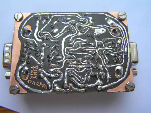
The circuit board is 71x49 mm.
SCHEMATIC DIAGRAM
To MENU
 CIRCUIT BOARD
To MENU
CIRCUIT BOARD
To MENU
TOP VIEW
To MENU
BOTTOM VIEW
To MENU
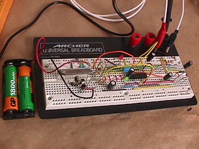
TESTS
To MENU
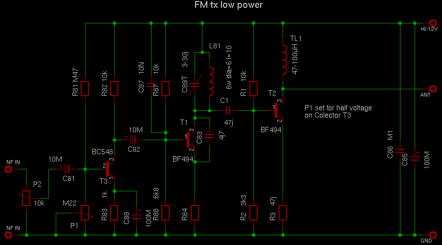
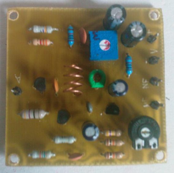
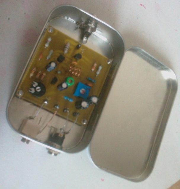
"Mini FM transmiter"
To Main MENU
Below is a small simple FM transmiter for a ship or home use to transmit
for example some news from HF radio to ship's FM receivers in the high seas.
Its range is about 100 meters.
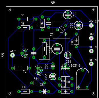
The circuit board is 55x55 mm. R84 is 47 oHm.
SCHEMATIC DIAGRAM
To MENU
 CIRCUIT BOARD
To MENU
CIRCUIT BOARD
To MENU
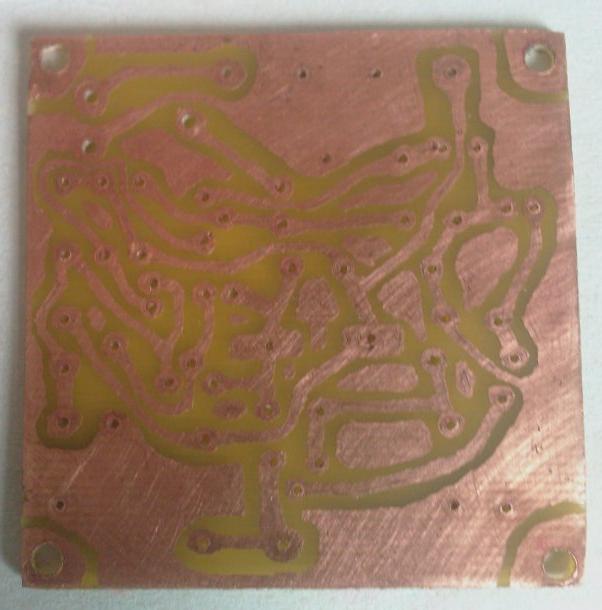
BOTTOM VIEW
To MENU
TOP VIEW
To MENU
BOX VIEW
To MENU
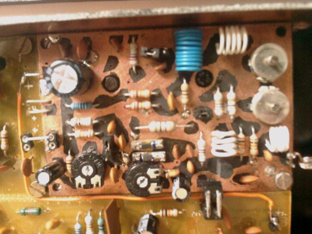
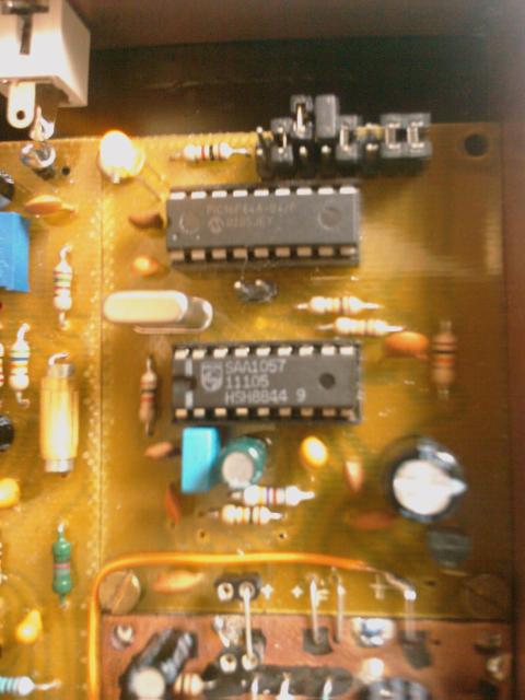
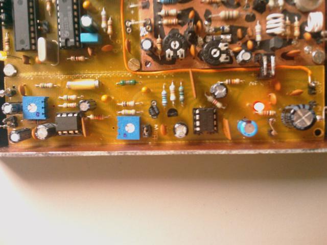
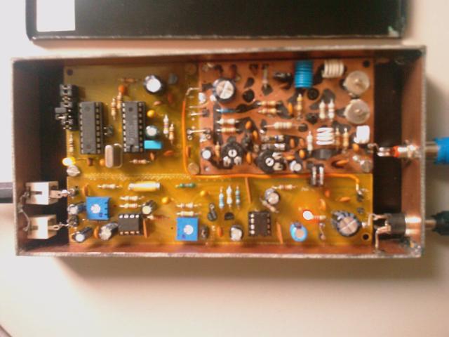
"Compact FM transmiter with PLL tuning"
To Main MENU
Below is a FM transmiter with PLL tuning for a ship or home use to transmit
for example some news from HF radio to ship's FM receivers in the high seas.
Its range is about 1 km with GP antenna. Firmware for PIC16F84 in asm and hex
format you can download as pll_soft.zip in the section
Downloads.
The circuit boards are joined into one board - see
picture.
TX SCHEMATIC DIAGRAM
To MENU
 TX BOARD DIAGRAM
To MENU
TX BOARD DIAGRAM
To MENU
 PLL SCHEMATIC DIAGRAM
To MENU
PLL SCHEMATIC DIAGRAM
To MENU
 PLL BOARD DIAGRAM
To MENU
PLL BOARD DIAGRAM
To MENU
 MODULATOR SCHEMATIC DIAGRAM
To MENU
MODULATOR SCHEMATIC DIAGRAM
To MENU
 MODULATOR BOARD DIAGRAM
To MENU
MODULATOR BOARD DIAGRAM
To MENU
 TX PART VIEW
To MENU
TX PART VIEW
To MENU
PLL PART VIEW
To MENU
MODULATOR PART VIEW
To MENU
COMPLET VIEW
To MENU
Best 73 de Libor OK2PEN
To MENU
THE PAGE IS FURTHER DEVELOPED ... --> -->
| | | | | | | |